Overview
I recently got a 3D printer. I had several reasons for getting it – like to play with a cool new technology – but I also had practical reasons like making things for fishing and for my boat Starting off on this journey I didn’t know how well it was going to work. I was going to have to learn how to use 3D modeling software, figure out how to 3d print in a stronger material, and test if the final product was going to be strong enough to be practical.
Downrigger Mount Setup
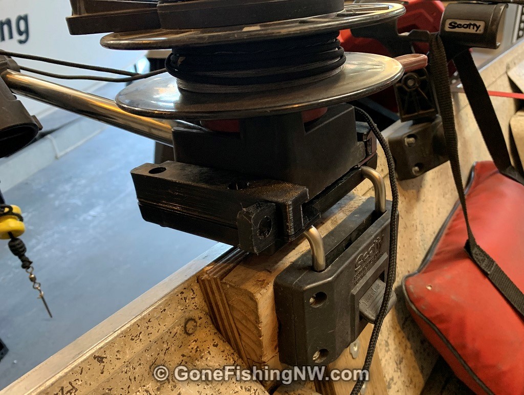
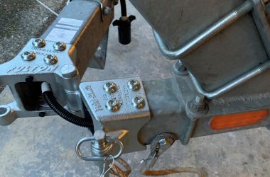
In my 12-foot rowboat that I take to small trout lakes I have a couple of Scotty manual downriggers mounted. They are attached to the boat with a Scotty Right Angle backet. That allows me to remove the downrigger and much of the mount when I don’t need them. That is helpful since it is less stuff for hooks to snag and fish to tangle with.
Unfortunately that bracket isn’t the complete story, as it also needs the Scotty Quick Slide Bracket which completes the top part of the mount. The base of the downrigger slides into the quick slide bracket. The white pin keeps it from sliding out accidently.
I have two of these mounted in the boat – one back where I sit and the only mounted on the front and other side for whoever is fishing with me.
Over the years these have taken a lot of abuse and the part of the white pin which sticks out has been broken off on one of them. This isn’t a big problem since I rarely slide the downriggers in and out of the mount. It hasn’t been worth the $20 to replace it.
I could have just 3D printed that one piece, but I thought this would be a good opportunity to see if the entire bracket could be 3d printed.
Introduction to 3D Printing
Now if you don’t know anything about 3D printing let me give you a quick introduction.
When most people think of 3D printing what they picture is FDM style printers. FDM stands for fused deposition modeling. It works by taking a strand of plastic – called filament – which gets fed into a hot nozzle – called the hot end or extruder. This melts the plastic gets added to the right spots on the model, where it hardens and builds up whatever it is your are printing.
A combination of extruder and bed movements can position the hot end anywhere in 3D space. Which allows it to deposit the material level by level, until the item is complete.
There is a variety of materials which can be printed with – most of them are different kinds of plastics which have different properties such as melting temperature, strength, and so on. There are also variants which have other material embedded in them such as bits of carbon fibers, wood or even metal. This gives the material different properties.
The most common material is called PLA which is relatively easy to print with, but isn’t very strong and doesn’t weather well. My goal is to use a stronger material which would be appropriate for long term outdoor use.
3D printing starts with a 3D model that one creates on a computer with special 3D modeling software. There is a variety of software out there, ranging from free to expensive. Some like TinkerCAD are designed for beginners while others are meant for more experienced users.
Once you have a 3D model, usually as a STL file, you import that into a slicer. The slicer is another software tool which breaks the 3d object into layers, with each layer consisting of detailed instructions on how to move the extruder to lay down that layer. These instructions are called gcode.
The gcode is then sent to the printer, which then starts doing its thing. 3D printing is a relatively slow process, with prints of reasonable size and complexity quickly reaching multiple hours. Larger objects can take days to print.
Because the material is laid down layer by layer, there can be a problem for parts of the object which overhang empty space. Because there is nothing to hold the plastic while it hardens it can droop down. The solution is called supports – simple structures the slicer generates to support these overhangs while printing. These are designed to breakaway after the printing, but sometimes it isn’t that easy.
Other problems people encounter while printing is warping, stringing, ghosting and materials not sticking to the print bed. There are different techniques to deal with these, but it often takes experience to know how to solve the problems, or even avoid the problems. That experience also help you know when to anticipate each problem, so you don’t find out after a 4 hour print.
Creating The Model
There are online catalogs of 3D models, some free and some paid. Since this is a very specific model, there was nothing existing. So I had to create the model myself. Since I came from an engineering background I thought that the 3D modeling tool OpenSAD would be the best fit for me. This allows you to describe the model in a simple programming language.
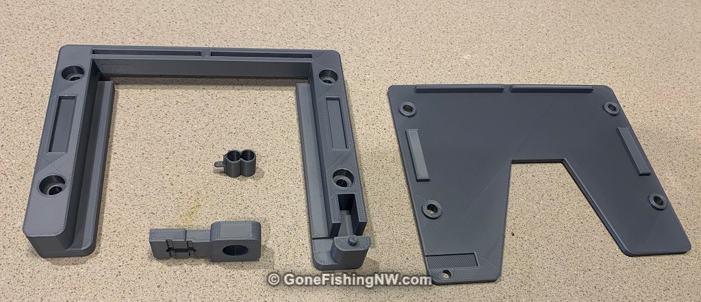
My methodology was simple, since I had existing parts to work with. I took apart the quick slide mount, so I could access all the pieces. It consists of 4 pieces – a top, a bottom, the sliding pin and what I called the spring which helps the pin snap into its 2 positions and not slide out.
Taking each piece in turn I use a micrometer to measure the various features of the piece. Generally speaking OpenSAD works by declaring shapes to combine together, or shapes to cutout of your piece. For example the spring consists of 2 cylinders side by side, with the inside cutout by 2 other cylinders, combined with a cube in front with a cylinder sticking out in front tipped with a sphere.
After each piece was modeled I’d print it in PLA using settings for a quick less detailed print. After it was printed I’d reassemble the quick slide bracket, but using that 3d printed piece with the other official pieces.

The first attempt of each piece always had an issue – too big, too small, holes not aligned, etc… So then I updated the model appropriately and reprinted. My plan was to repeat this iterative process until the parts all matched up – fortunately 2 rounds of prototyping was all it took.
I did this process for all 4 parts, and at the end wound up with a prototype that was fully compatible with the official parts. I tried to capture all the important features as close as possible. However the official version is largely hollow. I don’t know if this is to reduce costs, or make the manufacturing easier or what. I largely left my model solid, since 3D printing allows me to control how solid the interior is (called infill).
I’ve shared my final model online on Thingiverse.
Printing The Final Version
Now that my model was done, it is time to print the final version. I knew the PLA I was using for prototyping was not an appropriate material. In fact I did a little testing with the prototype and it broke pretty easy.
I decided to use nylon, which has a reputation for producing strong 3d printing parts. Unfortunately I didn’t know then how hard nylon is to successfully print with. The nylon I had bought for this was black, but it comes in a variety of colors.
I naively sliced my model with settings similar to what I used with the PLA, fired up the Prusa printer and started to print.
The first problem I had is that the first layer of the nylon wouldn’t stay stuck on the print bed, which fortunately I noticed quickly and canceled the rest of the print. I tried a variety of settings but none fully fixed the problem. Finally, I started resorting to a technique where you coat the print bed with glue stick before printing. That worked but was more work since I had to clean all that glue off afterwards.
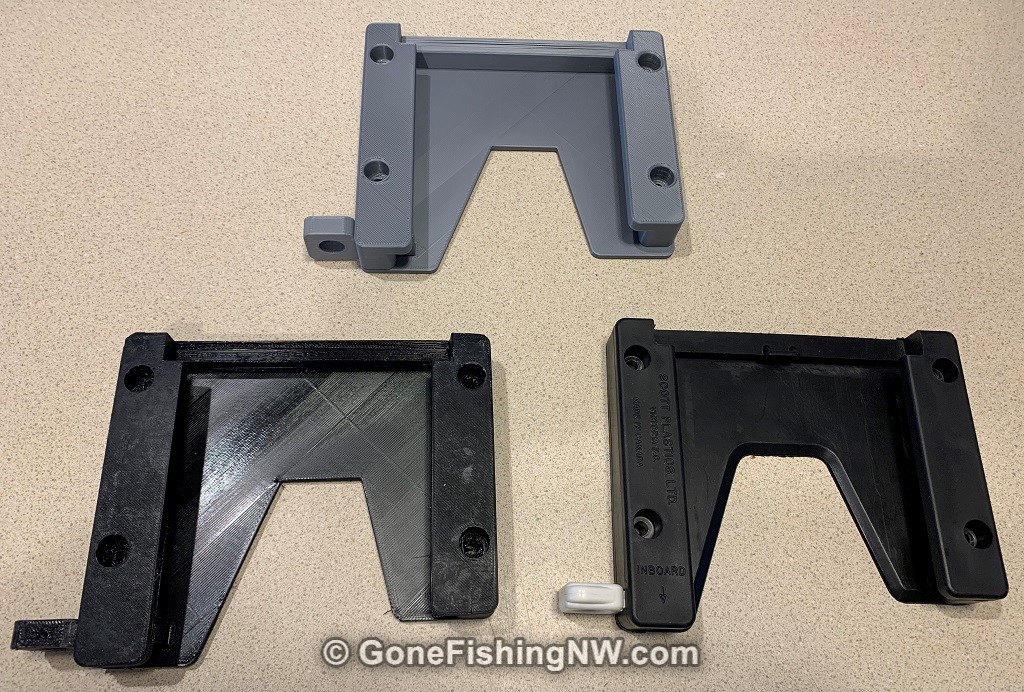
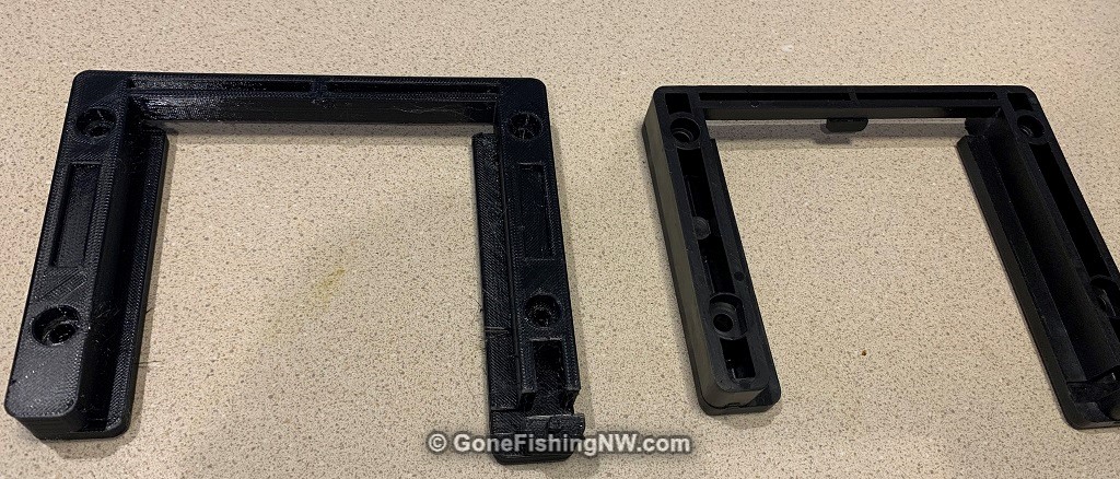
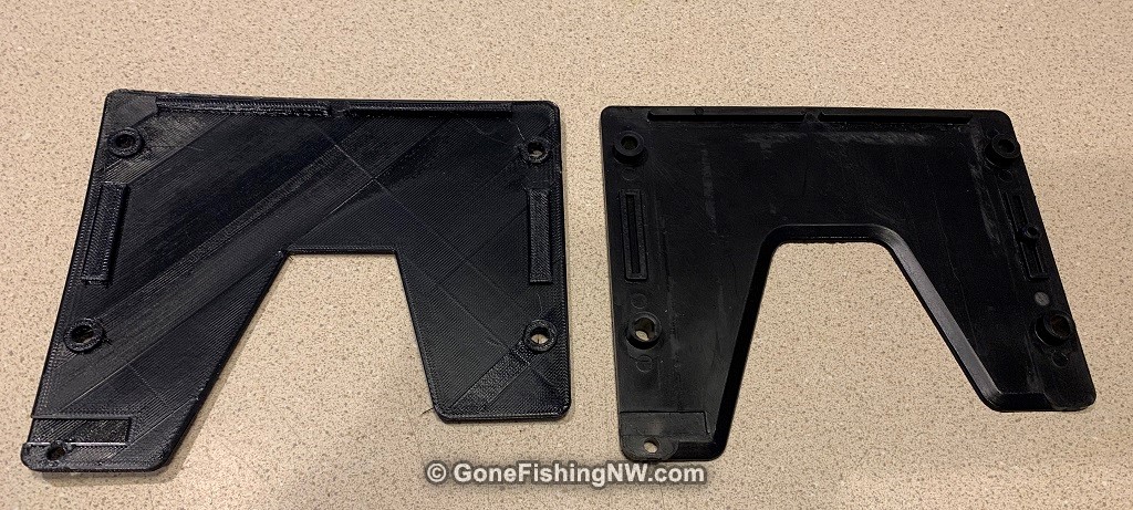
The next problem was the larger pieces – the top and bottom – would warp while printing. This would both mess up later layers, as well as result in an unusable part. The warping is result of cooling while printing, causing the plastic to contract. The best solution to this is to have an enclosure for the printer so the ambient temperature can be higher than room temperature. I didn’t want to go that far, so I employed two techniques. The first is a brim which is a single layer of plastic around the part you are printing to increase the force to hold the print to the bed. The second technique was a shield – a wall that gets built around the piece as it prints. That helps keep the heat around the part. Here you can see the original (right) and 3D printed (left) top and bottom side by side.
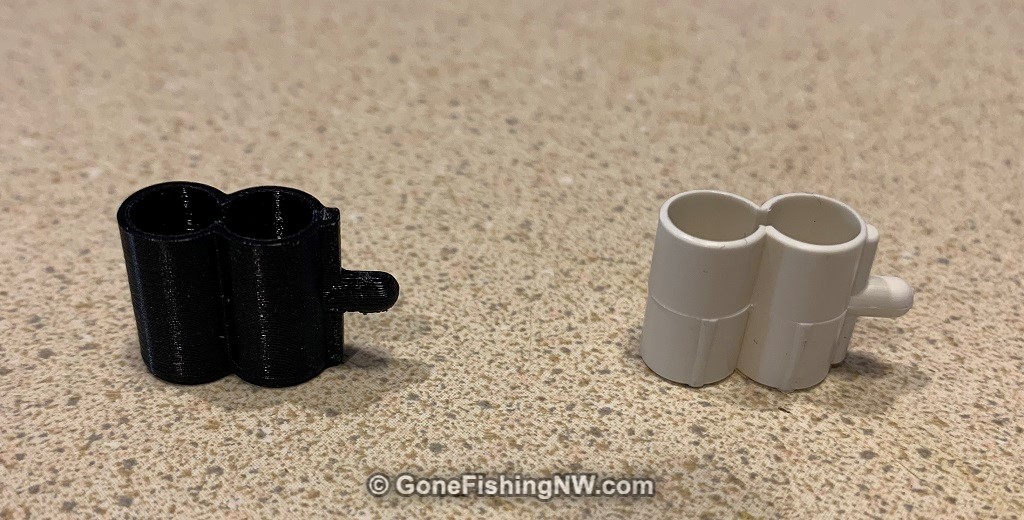
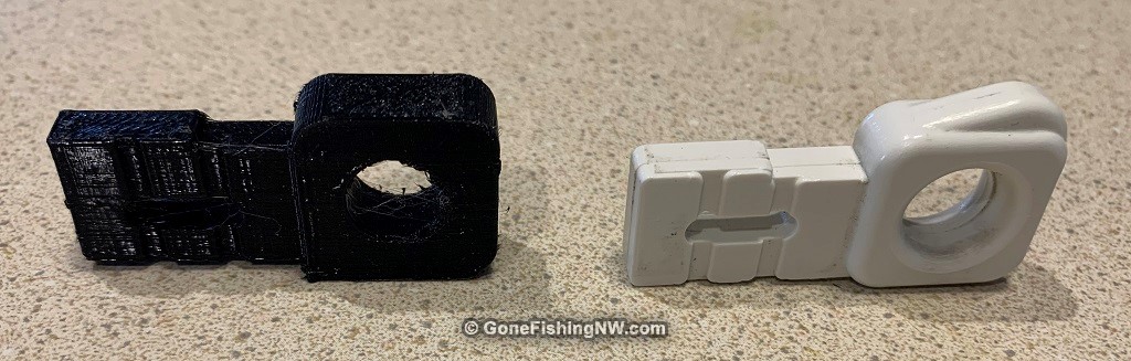
The last problem was the two smaller pieces – the spring and pin. These lacked the contact area with the print bed to stay in position during the print. Using the brim helped with that. These parts also had significant overhanging features which required me to add supports. The brims and supports generally broke away well, but I did have to clean up it just a little with a knife. Here you can see the original (right) and 3D printed (left) pin and spring side by side.
I printed all the pieces in a very obvious orientation focused on making the print successful, rather than the piece as strong as possible. 3D prints are usually weakest along the layer lines. I was worried that the top piece especially would be exposed to forces which would test that layer adhesion.
Testing The Mount
Now that I have all the pieces I then assembled them together, which went really well. I then attached it to the side mount. This is where I hit more problems. Somehow the two screw holes on one end of the bracket didn’t quite line up with the holes in the side mount. I’m not sure why this is, because the prototype holes lined up perfectly. Maybe I messed it up in a last minute tweak, or maybe the nylon contracted a bit more than the PLA. I didn’t want to spend another day reprinting the bracket, so I got out the drill out the overlap by drilling from the side bracket into the quick slide bracket.
I put the resulting assembly on the boat and slid the downrigger in. It fit perfectly.
I didn’t prepare any scientific testing technique, and I wasn’t going for a comparison in breaking strength with the original bracket. Instead I wanted to see how it would perform with the likely strongest forces it would ever encounter in real life. So holding the end of the downrigger I applied force forward and backwards, as well as down to simulate the downrigger ball getting snagged on something underwater and attempting to reel it up, or break it free with the (electric) motor.
With all the pushing and pulling the mount stayed together. I didn’t hear any pops or cracking. There was no visible effect on the parts. In fact I was more worried about how the side of the boat was flexing than what was happening on the downrigger mount.
After all that I’m confident that the 3d printed bracket could stand up to anything the original bracket was likely to encounter (and live through).
Lessons Learned
Overall I believe this project was a success. Not only was I able to 3d print a replacement for the broken mount piece, but I feel the entire 3d printed bracket is a reasonable replacement to the commercial one. The results also are a good indicator that my other planned projects, such as rod holders, have a good chance of turning out well.
After having gone through this experience for the first time I learned many things, which I will apply as I move forward with my other projects.
For the 3D modeling I learned that measurements less than a tenth of a millimeter don’t matter, since the printer doesn’t have that resolution. One should generally round up outer sizes and voids other pieces fit into. Inner sizes and parts that insert into other pieces should round down.
I also learned to intentionally introduce extra space for pieces which insert into each other. 0.1 mm for pieces which should have a snug fit and 0.2 mm for pieces which should move.
One thing I learned from a video afterwards is to build a slight taper into parts that fit into other parts to make them easier to insert. While that wasn’t a big problem, it would have been helpful.
For pieces which have common measurements such as the overall width and depth of the top and bottom brackets, or the screw holes which go all the way through, make sure to use the same measurements (ideally a shared constant) to ensure consistency.
For the actual 3D printing I wish I had started with PTEG material. It is much easier to print with, and also has a reputation for being a strong material. I’ll likely try this in future projects and then fall back to the nylon if the PTEG isn’t strong enough.
I’d also use a material other than boring black. If you are going to 3D print something like a downrigger bracket, might as well make it unique by printing it in hot pink or something. There is even glow in the dark filament which might be interesting when fishing in the dark – although it is probably best for non-structural parts.
I hope you found this article as interesting as I found the entire project, and consider if getting into 3d printing is something for you. I think it an exciting new technology that will make it much easier for hobbyist to fabricate custom parts, and enable repairs of items rather than having to replace
Pretty cool! I’ve just gotten into 3D printing myself for my other passion–building scale model airplanes. You’ve inspired me to look at my fishing kayak setups and see if I can’t innovate a solution to some issues I’ve had with some of my gear.