Years ago I read an article in a fishing magazine about how a guy mounted backup lights on his drift boat trailer, so he could see better when launching in the dark.
After getting a sled and doing several early morning launches at unlit boat launches I sympathized with his motivation. The light from your truck’s backup lights is feeble at best, and then blocked by the boat.
So I set out to make the same modification to my trailer, so I could actually see where I was backing up to.
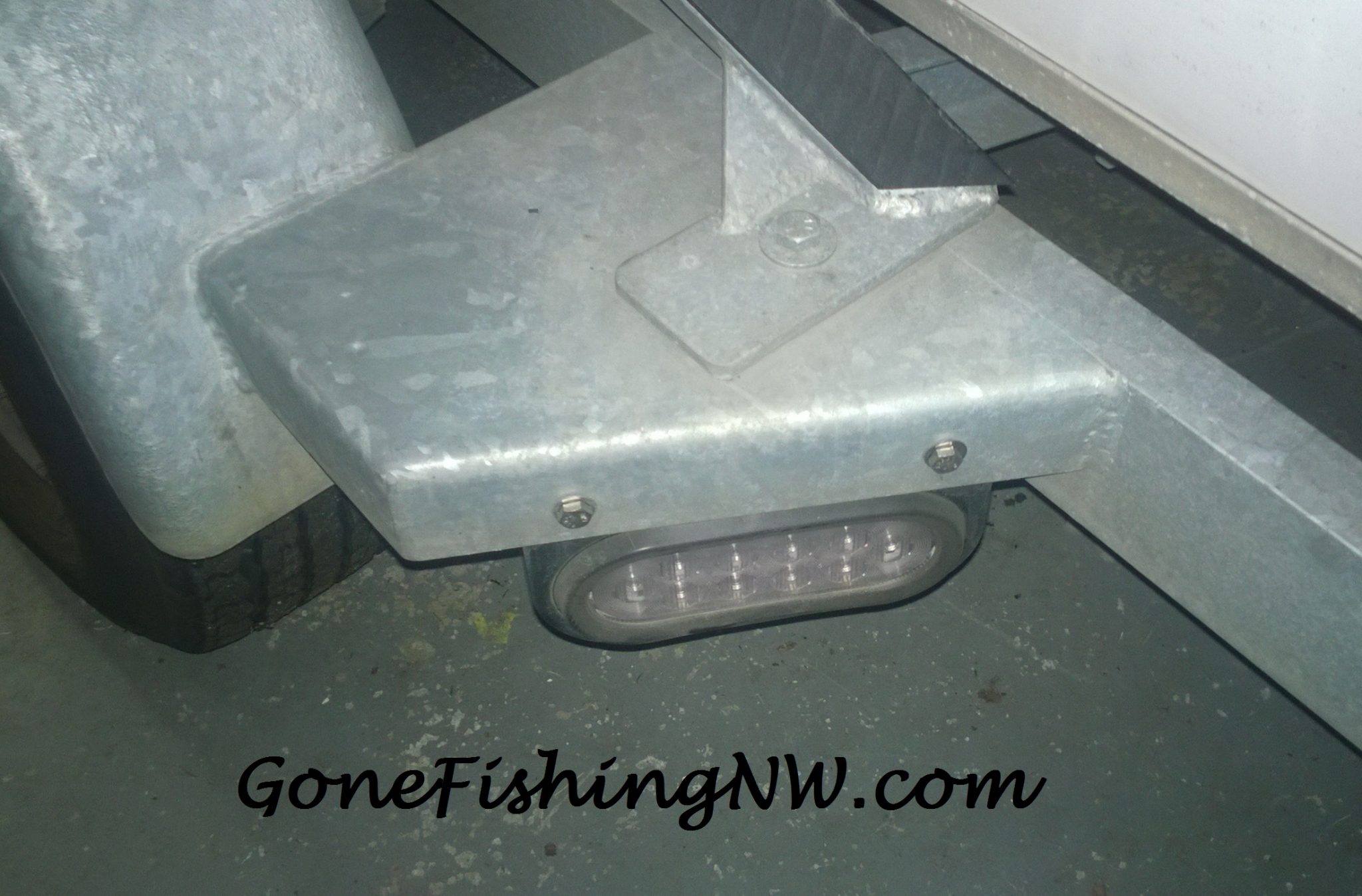
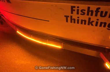
This is a picture of the final result.
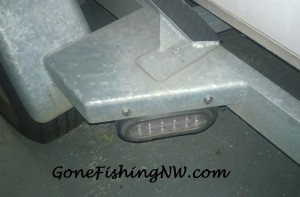
I’m writing this couple years later, so I don’t have pictures of all the various steps. So you will have to use your imagination a little. I was really pleased with the results. The lights have been very helpful on those dark mornings.
For more boat and trailer improvement projects I’ve done check out this page.
The first thing to know is that the common 4 pin trailer electrical connector used to connect the trailer to your truck does NOT support backup lights. The 4 plugs only support running lights, turn signals and brakes. You need a 7 blade (not pin) connector to support back up lights.
My truck already had a 7 blade receiver and I was using an adapter to connect the 4 pin trailer plug to my 7 blade receiver.
So the first step was to cut off the 4 pin plug, and wire in a replacement 7 blade plug.
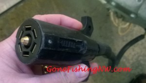
The wiring of the 7 blade plug is done according to this:
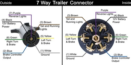
If your trailer follows the standard color code for the wiring then it should be easy to attach everything correctly. Since I was converting from 4 pin I had the following wires:
- Brown (tail & running lights)
- Yellow (left turn)
- Green (right turn)
- White (ground)
FYI, brake lights is simply left & right turn on together solid, instead of blinking. That is why only 4 wires are needed.
I left the brake controller & accessory (battery) connections unattached, since I don’t have those devices
I attached 2 new purple wires to the connection for the backup lights. 2 wires are needed because you need to run a wire down each side of the trailer. Because the wire was going to be exposed to water and road grime, I used marine grade wire. I believe 14 gauge is what I used.
Next was running the wires down each side of the trailer to the fender where I was going to install the lights. This wiring diagram can help explain how the wiring should look.

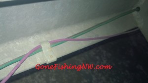
My trailer has an open frame, so running the wires was easy. I just ran it next to the existing wires. Every once in a while was a clip holding the wires to the frame. I just pulled the clip up with a screwdriver, slide the new wire in, and then let the clip go.
Occasionally was a cross beam in the trailer. The existing wires had a nice hole with a rubber grommet for them to run through. Unfortunately the hole wasn’t big enough for me to push the new wire through too. Instead of drilling a new hole simply went under the cross beam.
You can see the clip, and at the right how the wire goes under the cross beam.
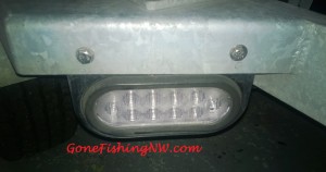
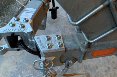
The holes at the top of the frame face up, but I needed to attach them to the side of the fender. So I had to get an L beam, similar to this. Holes were then drilled on each side of the L beam. One pair to attach it to the mounting bracket, and another pair to attach it to the fender. The holes were offset from each other, so to have space for the nuts and bolts. Matching holes were drilled in the fender. The beam was then painted so it wouldn’t rust.
Using stainless steel bolts and nylon lock nuts, I connected to the L bracket to the mounting bracket and the fender. Once those were in place, I was able to push in the light and it’s grommet into the mounting frame.
The final step is to complete the wiring.
The purple wire we ran down the trailer was connected to the red wire from the light with a heat shrink butt connector. Dielectric grease and good crimping was used to ensure a good connection. A heat gun was then used to shrink the tubing around the wire for a water proof fit.
The black wire connects to ground. On metal trailers ground is the frame itself, rather than a separate wire. We start by putting a heat shrink ring connector on the black wire, similar to how we did the butt connectors. Then we drill a small hole in the frame, just big enough for a sheet metal screw that matches the ring size. A little sandpaper should be used around the hole to ensure a good metal to metal connection. Rub some dielectric grease on, then attach the ring connector to the frame. Adding an extra coat of dielectric grease is a good thing.
Now attach the truck, and do your final testing. This is easiest with another person. Someone works the controls in the truck, and the other observes the lights. Make sure to verify:
- running lights
- left turn signal
- right turn signal
- brake lights
- backup lights
Hopefully everything worked well and the project is done.






Comments are closed.